Thrust vector control
A solid motor burns until it is empty, whatever direction the vehicle points. The gimbal points the thrust instead: a two-axis mount, two servos, pushrods, and a controller that works only while the motor burns.
3D schematic, not the real geometry.
-
01
The mechanism
The only control authority a solid motor offers is the direction of its thrust. The motor sits in a two-axis gimbal: two nested rings, each turned by one servo through a pushrod. Tilting the motor tilts the thrust line, and that turns the vehicle.
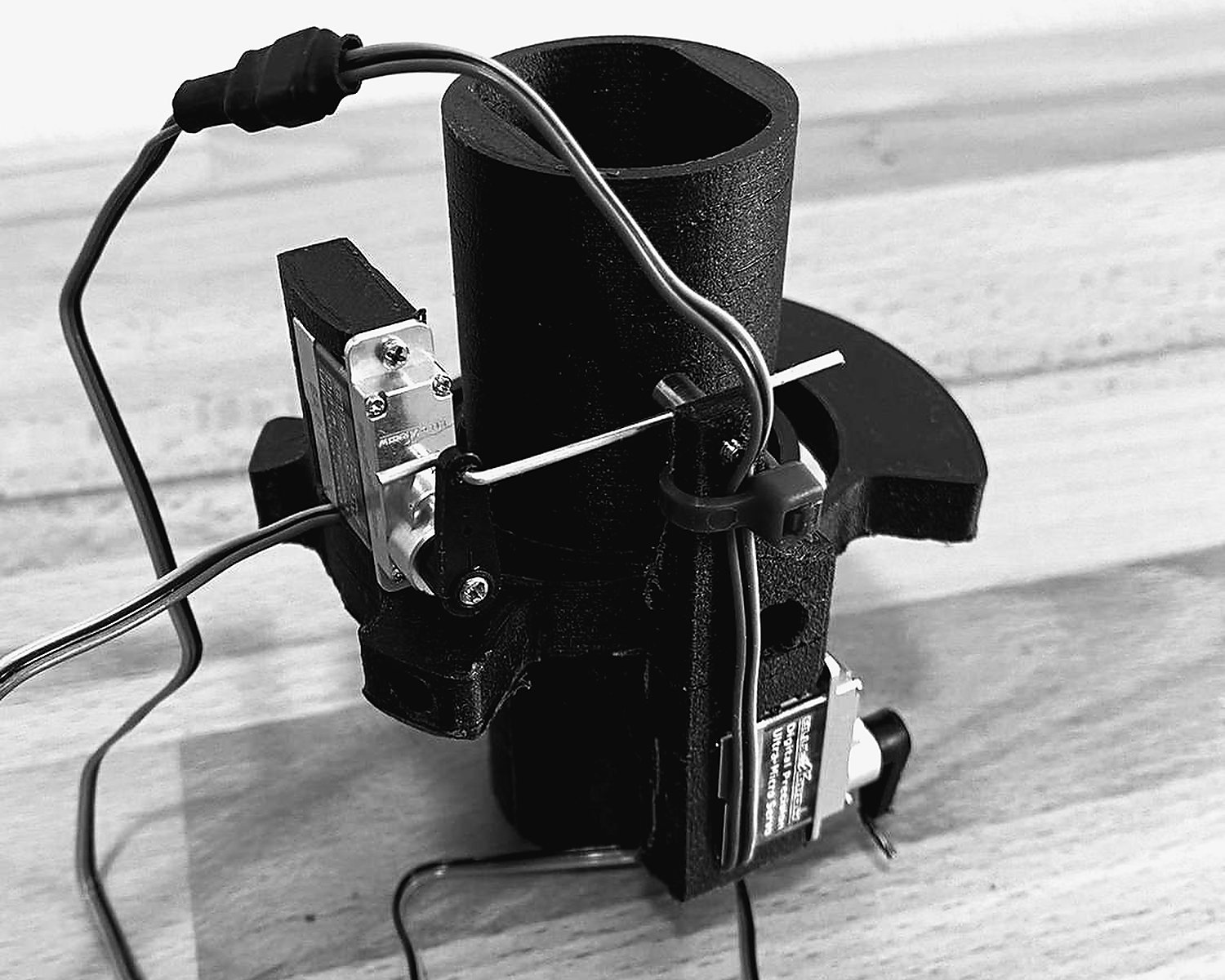
Fig. 2.1 — Gimbal mk10 · assembled hardware and CAD -
02
Sensing
Every cycle of the burn the flight computer takes pitch and yaw from the IMU. The measured attitude is compared with the target: straight up, zero degrees on both axes.
-
03
Control
Each axis has its own PID controller. The error between the measured angle and the target becomes a servo command: a proportional part for the present error, a derivative part that reacts to how quickly it changes, and an integral part for lasting offsets. The gains are tuned on the bench and read from the SD card at boot, so the vehicle can be retuned at the pad without a toolchain.
The animation is a schematic. Its gains and limits are illustrative, not the flight values.
-
04
Limits and self-test
Both axes are limited in software to a travel window around centre before anything is written to the servos, so a controller fault cannot drive the gimbal into its mechanical stops. At power-up the controller sweeps both axes through their range and back, a visible confirmation that the actuation path is live before the motor is armed. The gimbal is live only during powered flight: the servos attach at liftoff and are released at burnout.
-
05
Specification
- Revision
- mk10 (mk1 → mk10)
- Airframe
- 75 mm
- Axes
- 2 — pitch, yaw, independent
- Controller
- PID per axis, setpoint 0°
- Active
- powered flight only
- Tuning
- set from the SD card at boot
- Travel
- clamped each cycle before write
- Actuation
- 2 servos, pushrod-driven


